Chlorosilane Tail Gas Mist Eliminator: Protecting TCS Recovery Circuits in Polysilicon Plants
In Siemens process polysilicon production, the tail gas leaving the chemical vapor deposition (CVD) reactor is not waste — it is a recoverable feedstock stream containing unreacted trichlorosilane (TCS), silicon tetrachloride (SiCl₄), and hydrogen chloride (HCl). Recovering these components and returning them to the process is fundamental to the economics of polysilicon production.
The mist eliminator installed between the CVD reactor and the tail gas recovery circuit is one of the most technically demanding positions in the entire plant. Failure here means chlorosilane liquid carryover into the cold trap, contamination of the TCS recovery column, catalyst poisoning in the hydrochlorination reactor, and degraded polysilicon purity — cascading problems that affect yield, quality, and operating cost simultaneously.
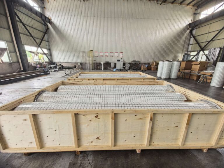
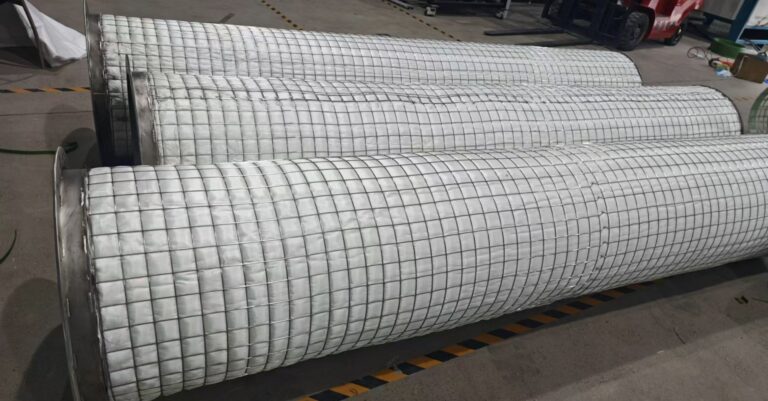
Filtearth engineers fiber bed mist eliminators specifically for chlorosilane tail gas service — with fiber specifications, inert atmosphere designs, and outlet performance targets engineered for the recovery circuit protection requirements of polysilicon production.
The Chlorosilane Tail Gas Stream
Composition
The tail gas stream leaving a Siemens CVD reactor contains:
- Hydrogen (H₂): 80–90% by volume — the carrier gas for TCS deposition
- Trichlorosilane (SiHCl₃, TCS): 5–15% — unreacted feedstock
- Silicon tetrachloride (SiCl₄, STC): 2–8% — byproduct of the deposition reaction
- Dichlorosilane (SiH₂Cl₂, DCS): Trace quantities
- Hydrogen chloride (HCl): 1–3%
- Liquid chlorosilane aerosols: Fine droplets of TCS, STC, and mixed chlorosilanes generated by condensation at the cooler reactor outlet conditions
The liquid aerosol fraction — droplets ranging from 0.1 to 10 microns — is what the mist eliminator must capture. These droplets, if not removed, enter the cold trap and tail gas compression system as liquid carryover, causing the operating problems described below.
Why Chlorosilane Aerosols Are Particularly Challenging
Chlorosilane aerosols present two characteristics that make them more difficult to capture than standard industrial acid mist:
Low droplet density: Chlorosilane liquids are significantly less dense than water-based acid solutions. Lower liquid density reduces the inertial impaction efficiency for a given droplet size — meaning that a chlorosilane droplet of 2 microns behaves more like a 1 micron water droplet in terms of its ability to follow gas streamlines around fiber surfaces. This shifts the collection burden toward the Brownian diffusion mechanism, requiring finer fiber grades and lower face velocities than equivalent water-based mist service.
Moisture reactivity: Chlorosilanes react rapidly with water to produce HCl and silicon oxide (SiO₂):
SiHCl₃ + H₂O → SiO₂ + 3HCl
Any moisture that contacts chlorosilane-wetted fiber surfaces generates HCl gas and deposits silicon oxide on the fiber. Silicon oxide deposits are not soluble and cannot be drained — they accumulate on fiber surfaces, progressively increasing pressure drop and eventually blinding the fiber bed. Preventing moisture ingress is therefore as important as the fiber specification itself.
Consequences of Inadequate Chlorosilane Mist Elimination
Cold Trap Contamination
The cold trap downstream of the mist eliminator condenses and recovers chlorosilane vapors from the tail gas. Liquid chlorosilane aerosol carryover from the mist eliminator enters the cold trap as fine droplets that are difficult to distinguish from vapor-phase condensate. This liquid carryover contains whatever impurities are present in the CVD reactor gas — including metal chloride traces from heated rod surfaces. These impurities contaminate the recovered TCS, degrading its purity below the specification required for reuse as polysilicon feedstock.
Hydrochlorination Catalyst Poisoning
Recovered silicon tetrachloride is converted back to trichlorosilane in the hydrochlorination reactor using a copper-based catalyst. Liquid carryover from the mist eliminator that reaches the hydrochlorination reactor introduces contaminants — particularly metal chlorides and silicon oxide particles — that degrade catalyst activity over time. Catalyst replacement in a hydrochlorination reactor requires an extended shutdown and represents a significant maintenance cost.
Tail Gas Compressor Damage
The tail gas compressor that circulates hydrogen and chlorosilane vapors through the recovery loop operates under conditions where liquid slugging is highly damaging. Liquid chlorosilane droplets entering the compressor suction cause valve damage, seal degradation, and impeller erosion. Compressor maintenance in chlorosilane service is hazardous and expensive — a single liquid slug event can require major compressor internals replacement.
Polysilicon Quality Impact
Trace metal contamination introduced through inadequate mist elimination at the tail gas recovery circuit ultimately appears as elevated metal concentration in the finished polysilicon product. For electronic-grade polysilicon with metal specifications in the parts-per-trillion range, contamination sources anywhere in the closed-loop recovery circuit must be minimized.
Filtearth Engineering Solution for Chlorosilane Tail Gas Service
Fiber Specification
Filtearth proprietary glass fiber — fine grade (3–8 μm diameter)
Fine fiber diameter maximizes Brownian diffusion efficiency for the submicron chlorosilane aerosol fraction — the most difficult size range to capture and the fraction most responsible for cold trap and compressor contamination.
The fine fiber grade is selected for:
- High collection efficiency for droplets below 1 micron through Brownian diffusion
- Low contamination potential — the proprietary glass fiber formulation minimizes metallic impurity contribution to the recovered chlorosilane stream
- Chemical resistance to TCS, STC, HCl, and DCS at CVD reactor outlet conditions
- Mechanical stability under continuous gas flow without fiber migration or compaction
Target outlet performance: Chlorosilane mist concentration below 1 mg/Nm³ — the performance level required for cold trap and compressor protection in high-purity polysilicon production.
Inert Atmosphere Design
The single most important design feature for chlorosilane tail gas mist eliminators is the prevention of moisture contact with chlorosilane-wetted surfaces.
Filtearth designs chlorosilane tail gas mist eliminators with:
Nitrogen purge connections: Top and bottom purge nozzles allow the vessel interior to be blanketed with dry nitrogen during startup, shutdown, and maintenance periods. Nitrogen blanketing prevents moisture ingress from ambient air and eliminates the HCl generation and SiO₂ deposition that would otherwise occur when chlorosilane-wetted fiber surfaces contact moisture.
Sealed drain system: The liquid drain from the fiber bed sump is connected to a closed chlorosilane collection system — not vented to atmosphere. The drain system maintains a liquid seal or uses a nitrogen-pressurized seal pot to prevent air ingress through the drain connection.
Gasketing and sealing: All vessel flanges, inspection ports, and instrument connections are sealed with materials compatible with chlorosilane service to prevent moisture ingress during operation.
Shell and Support Materials
| Component | Material | Reason |
|---|---|---|
| Vessel shell | SS316L or Hastelloy C-276 | TCS, STC, HCl resistance at operating temperature |
| Inner and outer screens | SS316L electropolished | Low contamination potential, HCl resistance |
| End plates | SS316L | Matched to vessel material |
| Flange connections | ANSI 150# or 300# SS316L | Standard for polysilicon plant connections |
| Gaskets | PTFE or Viton | Chlorosilane resistance |
| Nitrogen purge nozzles | SS316L | Inert purge system integration |
| Drain connection | SS316L with closed seal system | Closed chlorosilane recovery |
Operating Specifications
| Parameter | Specification |
|---|---|
| Fiber material | Filtearth proprietary glass fiber (fine grade) |
| Fiber diameter | 3–8 μm |
| Collection efficiency | > 99.96% |
| Target outlet concentration | < 1 mg/Nm³ |
| Droplet capture range | 0.1–3 μm |
| Operating temperature | -20°C to 80°C |
| Design pressure | Up to 10 bar g (higher on request) |
| Shell material | SS316L |
| Inert purge | Nitrogen purge connections standard |
| Element diameter range | 200–1,500 mm |
Installation Position in the Polysilicon Plant
Primary Position: CVD Reactor Outlet to Cold Trap
The most critical installation position is between the CVD reactor outlet cooler and the cold trap inlet. At this position, the gas stream is at its coldest operating temperature — maximizing chlorosilane condensation into liquid aerosols — and the mist eliminator must achieve its lowest outlet concentration to protect the cold trap and downstream equipment.
Secondary Position: Hydrochlorination Reactor Vent
The vent gas from the hydrochlorination reactor contains STC vapor and HCl. A secondary fiber bed mist eliminator on this vent stream prevents STC liquid carryover to the vent scrubber and protects the scrubber packing from liquid slugging.
Bypass Protection
Filtearth recommends installing isolation valves on each mist eliminator to allow the unit to be taken offline for inspection or element replacement without shutting down the polysilicon plant. A bypass line with appropriate valving allows the tail gas circuit to continue operating during mist eliminator maintenance — though at reduced mist elimination performance — without a full plant shutdown.
Comparison: Wire Mesh vs. Fiber Bed in Chlorosilane Service
| Performance Metric | Wire Mesh Demister | Filtearth Fiber Bed |
|---|---|---|
| Effective droplet size | > 5 μm | 0.1–3 μm |
| Collection efficiency | 50–80% | > 99.96% |
| Outlet concentration | 20–100 mg/Nm³ | < 1 mg/Nm³ |
| Moisture sensitivity | Low | High — requires inert purge design |
| Cold trap protection | Inadequate | Effective |
| Compressor protection | Partial | Effective |
| Service life | 2–3 years | 3–5 years |
Wire mesh demisters are frequently installed in polysilicon plants as the first-generation mist elimination solution. Their limitations in capturing submicron chlorosilane aerosols are responsible for the majority of cold trap contamination and compressor liquid slugging events in operating polysilicon facilities.
Frequently Asked Questions
What causes silicon oxide deposits to form inside a chlorosilane mist eliminator? Silicon oxide deposits form when chlorosilane liquid on fiber surfaces contacts moisture. The reaction SiHCl₃ + H₂O → SiO₂ + 3HCl produces solid silicon oxide that accumulates on fiber surfaces and cannot be redissolved or drained. Prevention requires complete exclusion of moisture through nitrogen blanketing during all non-operating periods. Once silicon oxide deposits form, element replacement is the only remedy.
What fiber material does Filtearth use for chlorosilane tail gas service? Filtearth uses proprietary glass fiber in fine-diameter grades (3 to 8 microns) for chlorosilane tail gas service. The fiber formulation provides chemical resistance to TCS, STC, HCl, and DCS while minimizing metallic contamination contribution to the recovered chlorosilane stream.
Can the collected chlorosilane liquid be returned to the process? Yes. The chlorosilane liquid collected in the fiber bed sump is clean TCS/STC mixture that can be returned directly to the chlorosilane recovery circuit. The drain system must be connected to a closed collection vessel to prevent air contact. Filtearth designs the drain system for closed-loop chlorosilane recovery as standard for polysilicon applications.
What outlet concentration can Filtearth units achieve in chlorosilane service? Filtearth fiber bed mist eliminators for chlorosilane tail gas service are designed to achieve outlet concentrations below 1 mg/Nm³ for chlorosilane aerosols in the 0.1 to 3 micron range. Actual outlet concentration depends on inlet loading, operating face velocity, and fiber bed specification confirmed during engineering design.
How is the mist eliminator element replaced without a full plant shutdown? Filtearth recommends installing isolation and bypass valves on each mist eliminator to allow element replacement during planned maintenance windows without shutting down the tail gas recovery circuit. The element replacement procedure requires nitrogen purging of the vessel before opening, followed by safe removal of the spent element and installation of the new element under nitrogen atmosphere. Full replacement including purging and re-pressurization typically takes 4 to 8 hours.
Can Filtearth supply chlorosilane mist eliminators for fluidized bed reactor polysilicon plants? Yes, but the specification differs from Siemens process service. Fluidized bed reactor off-gas contains silicon dust in addition to chlorosilane mist, requiring a coarse fiber grade with higher solids tolerance and a pre-separator upstream of the fiber bed to handle silicon particle loading. Contact Filtearth with your FBR process data for a specific engineering recommendation.
Request a Technical Quotation
If you are evaluating fiber bed mist eliminators for chlorosilane tail gas service in a Siemens process or fluidized bed reactor polysilicon plant, Filtearth is ready to provide a detailed technical proposal within 24 hours.
To receive a quotation, please provide:
- Production process (Siemens CVD or fluidized bed reactor)
- Tail gas composition (TCS, STC, HCl concentrations)
- Gas flow rate (m³/h or Nm³/h)
- Operating temperature and pressure
- Required outlet chlorosilane mist concentration
- Installation position (CVD outlet, hydrochlorination vent, or other)
- Existing vessel dimensions (for retrofit applications)
Contact Henry Wang directly: Email: [email protected] WhatsApp: +86 159 365 10880
Response within 24 hours. Inert atmosphere design included as standard for all chlorosilane applications.