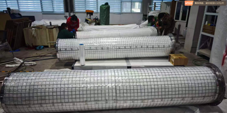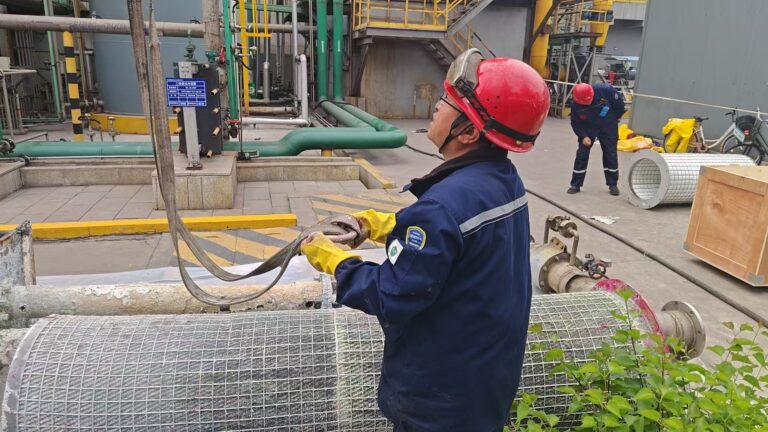
Fiber Bed Mist Eliminator Pressure Drop: Engineering for High-Velocity and Pressure-Constrained Applications
Pressure drop across a fiber bed mist eliminator is not a secondary specification — it is a primary design constraint that determines whether a unit can operate in a given system at all. Exceed the system pressure drop limit and the blower overloads, throughput drops, and the drying tower or absorption column destabilizes. Install a unit that meets the pressure drop limit but sacrifices collection efficiency, and the plant fails emission tests.
Getting both right simultaneously — 99.96% collection efficiency within a hard pressure drop limit — requires application-specific engineering, not catalog selection.
This article explains the physics of fiber bed pressure drop, the variables that control it, the counterintuitive design decisions that optimize it at high gas velocities, and the field data from a documented retrofit installation that demonstrates what correctly engineered pressure drop management delivers in practice.
What Determines Fiber Bed Pressure Drop
Pressure drop across a fiber bed mist eliminator is governed by five interacting variables. Understanding how each contributes allows engineers to optimize the design for constrained applications.
1. Superficial Gas Velocity
Gas velocity is the dominant variable. Pressure drop increases approximately with the square of superficial velocity — doubling gas velocity quadruples pressure drop. For systems operating above original design velocity — due to capacity expansion, changed feed gas composition, or original design conservatism — this relationship explains why pressure drop problems emerge suddenly rather than gradually.
At the face velocities typical of industrial fiber bed installations (0.1 to 2.5 m/s), the pressure drop relationship with velocity is well-characterized and predictable from fiber bed geometry. What is less intuitive is how the other four variables can be used to offset the velocity effect.
2. Fiber Diameter
Finer fibers create higher pressure drop at constant packing density because they present more surface area to gas flow per unit volume. A bed of 3 μm fibers at the same packing density as a bed of 15 μm fibers generates significantly higher resistance to gas flow.
This creates an apparent conflict: finer fibers are required for high submicron collection efficiency (through enhanced Brownian diffusion and interception), but finer fibers also generate higher pressure drop. Resolving this conflict is the central challenge of fiber bed design for high-velocity, pressure-constrained service.
3. Packing Density
Higher packing density — more fiber mass per unit volume — increases both collection efficiency and pressure drop. Packing density is the most direct lever for adjusting the efficiency-pressure drop tradeoff in a given fiber grade.
For pressure-constrained applications, reducing packing density in combination with other design adjustments can reduce pressure drop while partially compensating the efficiency reduction through other mechanisms.
4. Bed Thickness
Greater bed thickness increases both pressure drop (proportionally) and collection efficiency (through extended residence time for Brownian diffusion). For submicron-dominated mist service, bed thickness is the primary lever for adjusting Brownian diffusion efficiency independently of pressure drop per unit length.
The counterintuitive implication: reducing bed thickness reduces pressure drop but also reduces Brownian diffusion residence time. For high-velocity service where Brownian diffusion efficiency is already reduced by shorter residence time, further reducing bed thickness compounds the efficiency loss. The correct response to high velocity and constrained pressure drop is not simply to reduce bed thickness — it is to re-optimize fiber grade and packing density for the new operating velocity.
5. Liquid Loading
A dry fiber bed generates its design pressure drop based on fiber geometry and gas velocity alone. As liquid accumulates on fiber surfaces during operation, the effective fiber bed porosity decreases and pressure drop rises above the dry value. At high liquid loading, partially flooded fiber beds can generate pressure drops two to three times the dry design value.
Liquid loading pressure drop is not a design variable — it is an operating variable that must be managed through proper drainage design. A fiber bed that generates 800 Pa dry pressure drop and operates with adequate drainage will stay near 800 Pa throughout its service life. The same unit with inadequate drainage will progressively increase to 1,500 Pa or more as liquid accumulates.
Typical Pressure Drop Ranges by Application
| Application | Typical Operating Pressure Drop |
|---|---|
| Sulfuric acid absorption tower (standard) | 300–600 Pa |
| Sulfuric acid drying tower (standard) | 400–800 Pa |
| Chlor-alkali drying tower | 300–600 Pa |
| Amine absorber overhead | 200–500 Pa |
| Phosphoric acid concentrator | 400–700 Pa |
| Polysilicon tail gas (low velocity design) | 200–500 Pa |
| High-velocity retrofit (custom design) | 800–1,400 Pa |
The High-Velocity Design Problem
Why Plants Exceed Design Velocity
Most fiber bed mist eliminators are specified and installed during original plant design for a defined design gas flow rate. Over the plant operating life, actual throughput frequently exceeds the original design basis — due to debottlenecking, market demand, or operational improvements.
When gas flow rate increases above the original design basis, superficial velocity through the fiber bed increases proportionally. A unit designed for 0.8 m/s face velocity operating at 1.2 m/s — a 50% throughput increase — experiences pressure drop approximately 2.25 times the design value. A unit designed for 800 Pa now generates approximately 1,800 Pa.
If the system pressure drop budget is 1,450 Pa, the unit is now 350 Pa over limit.
This is precisely the situation Filtearth resolved in the Kazakhstan sulfuric acid plant retrofit.
The Kazakhstan Retrofit: Documented Case Data
Plant: Sulfuric acid production facility, Kazakhstan Application: Drying tower fiber bed mist eliminator replacement Problem: Gas velocity in the drying tower was significantly above standard design parameters. Standard 50 mm fiber bed elements at this velocity generated operating pressure drop of approximately 1,800 Pa — exceeding the system pressure drop limit of 1,450 Pa.
The constraint: Pressure drop must be below 1,450 Pa. Collection efficiency must be maintained at 99.96%. The fiber bed must fit the existing vessel without structural modification.
Standard solution: Replace like-for-like with standard 50 mm elements. Result: 1,800 Pa — system limit exceeded. Not viable.
Incorrect intuitive solution: Simply reduce bed thickness to 25 mm to reduce pressure drop. Result: pressure drop within limit, but collection efficiency drops significantly because the thinner bed at higher face velocity provides insufficient residence time for Brownian diffusion of submicron acid mist.
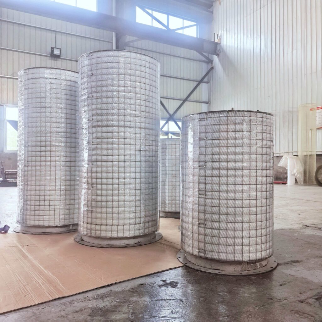
Filtearth engineering solution: Reduce bed thickness to 25 mm AND re-specify fiber grade and packing density for the higher face velocity — selecting a combination that maintains 99.96% collection efficiency at the new face velocity through optimized inertial impaction and interception, partially compensating for the reduced Brownian diffusion residence time.
Documented Performance Results
| Parameter | System Limit | Standard 50 mm | Filtearth 25 mm Custom |
|---|---|---|---|
| Operating pressure drop | < 1,450 Pa | ~1,800 Pa ❌ | ~1,200 Pa ✅ |
| Mist removal efficiency | ≥ 99.96% | ≥ 99.96% | ≥ 99.96% ✅ |
| Operational status | Continuous | — | Stable ✅ |
| Bed thickness | — | 50 mm | 25 mm (custom) |
| Elements installed | — | — | 7 units |
The custom 25 mm design achieved 1,200 Pa — 250 Pa below the system limit and 600 Pa below the standard design. Seven elements installed. Stable continuous operation confirmed post-commissioning.
Engineering Principles for Pressure-Constrained Design
The Kazakhstan case illustrates several principles that apply to any pressure-constrained fiber bed design:
Principle 1: Velocity-Specific Fiber Selection
At elevated face velocity, the inertial impaction mechanism becomes more dominant relative to Brownian diffusion. This changes the optimal fiber diameter for a given efficiency target. Fiber grades that are optimal at standard velocity are not optimal at elevated velocity — they may generate excessive pressure drop without providing proportionally higher efficiency at the new operating point.
Re-optimizing fiber diameter for the actual operating velocity — rather than applying a standard specification — is the starting point for pressure-constrained design.
Principle 2: Bed Thickness Reduction Is Not Enough Alone
Reducing bed thickness lowers pressure drop but also reduces Brownian diffusion residence time. At elevated velocity, Brownian diffusion residence time is already reduced. Further reducing it through thinner bed design compounds the efficiency loss.
Bed thickness reduction must be combined with fiber grade adjustment to maintain efficiency at the reduced thickness and higher velocity. These two variables must be co-optimized — not adjusted independently.
Principle 3: Packing Density as the Fine-Tuning Variable
After selecting the optimal fiber diameter and bed thickness for the velocity and efficiency target, packing density provides the fine-tuning lever. Incrementally adjusting packing density shifts the pressure drop vs. efficiency tradeoff within the design space defined by the fiber and thickness choices.
Principle 4: Drainage Design Is a Pressure Drop Variable
Liquid loading pressure drop — the additional pressure drop caused by liquid accumulation in the fiber bed beyond the dry design value — can be controlled through drainage design. Oversized drain nozzles, self-draining sump geometry, and elimination of liquid seal points in the drain piping minimize liquid accumulation and keep operating pressure drop close to the dry design value throughout the service life.
In pressure-constrained systems, the difference between a properly drained unit (operating at 1,200 Pa) and a poorly drained unit (operating at 1,800 Pa) is the difference between within-limit and over-limit operation — even when the fiber bed specification is identical.
System Pressure Drop Budget: How to Calculate Your Limit
Before specifying a fiber bed mist eliminator for a pressure-constrained system, the available pressure drop budget must be calculated from the system hydraulics.
Components of System Pressure Drop Budget
The total pressure drop budget available for the mist eliminator is:
Available ΔP = Blower/fan capacity − Σ(all other system pressure drops)
Other system pressure drops include:
- Ductwork and piping friction losses
- Vessel nozzle pressure drops
- Wire mesh pre-separator pressure drop (if installed)
- Heat exchanger pressure drops
- Control valve pressure drops
Typical available pressure drop budget for a fiber bed mist eliminator in sulfuric acid plant service: 500 to 1,500 Pa, depending on system design. Plants with older, lower-capacity blowers may have budgets as low as 300 to 500 Pa.
Operating Margin
Filtearth recommends designing the fiber bed for a pressure drop target of 80% of the available budget — providing a 20% operating margin for liquid loading above the design basis and for pressure drop increase over the element service life as fouling develops.
For the Kazakhstan system: limit 1,450 Pa × 80% = 1,160 Pa target. Achieved: 1,200 Pa — within 3% of the target.
When to Commission a Custom Pressure Drop Engineering Study
A custom pressure drop engineering study is warranted when:
- Current operating pressure drop exceeds or approaches the system limit
- Plant throughput has increased above the original fiber bed design basis
- Replacement of a failed or worn element must meet a tighter pressure drop limit than the original design
- Available pressure drop budget is below 500 Pa (low-budget blower systems)
- The fiber bed must be installed in an existing vessel with a diameter constraint that forces higher face velocity than standard designs accommodate
Filtearth provides custom pressure drop engineering as standard for all non-standard applications — not as a premium add-on service.
Frequently Asked Questions
How do I measure the current pressure drop across my fiber bed mist eliminator? Install differential pressure gauges or transmitters with tapping points on the gas inlet and outlet nozzles of the fiber bed vessel. The difference between inlet and outlet static pressure at operating flow rate is the operating pressure drop. For vessels without installed pressure taps, portable differential pressure instruments can be connected during a brief maintenance access period.
My fiber bed pressure drop has increased significantly over the past year. What is causing it? Rising pressure drop has two primary causes: liquid accumulation (drainage restriction) and solid fouling. Check the drain system first — ensure the drain valve is fully open, the drain line has no siphon points or liquid seals, and the drain is flowing freely. If drainage is confirmed free and pressure drop continues to rise, solid fouling of the fiber is likely and element replacement should be planned.
Can I reduce my fiber bed pressure drop by increasing the vessel diameter? Yes — increasing vessel diameter increases fiber bed face area, reducing face velocity at the same gas flow rate, which reduces pressure drop. This is a viable option for new installations where vessel sizing has not been finalized. For existing vessels, it requires vessel replacement and is typically less cost-effective than re-engineering the fiber bed specification for the existing vessel diameter.
What is the relationship between pressure drop and collection efficiency in a fiber bed? Higher pressure drop generally correlates with higher collection efficiency — because both increase with finer fiber, higher packing density, and greater bed thickness. However, this relationship is not fixed. Through fiber grade and packing density optimization, it is possible to achieve equivalent collection efficiency at significantly lower pressure drop by adjusting the balance between inertial impaction and Brownian diffusion mechanisms.
Does Filtearth guarantee the pressure drop performance of custom-designed units? Yes. Filtearth provides calculated design pressure drop values for all custom-engineered units based on actual process data. For installations where performance verification is required, post-commissioning differential pressure measurement confirms that operating pressure drop meets the design specification.
Request a Pressure Drop Engineering Assessment
If your fiber bed mist eliminator is approaching or exceeding its system pressure drop limit — or if you are specifying a new unit for a pressure-constrained application — Filtearth is ready to provide a custom pressure drop engineering assessment and quotation within 24 hours.
To receive an assessment, please provide:
- Current operating pressure drop (Pa)
- System pressure drop limit (Pa)
- Gas flow rate (m³/h or Nm³/h) at current and design conditions
- Vessel internal diameter (mm)
- Current fiber bed thickness (mm) and fiber specification (if known)
- Process gas type and operating temperature
Contact Henry Wang directly: Email: [email protected] WhatsApp: +86 159 365 10880
Custom pressure drop calculation provided at no cost. Kazakhstan retrofit case data available on request.